
SPW682-131 Mechanical Seal – HydroMax Industrial Pump Seal Solution
SPW682-131 Mechanical Seal – HydroMax Industrial Pump Seal Solution
Overview
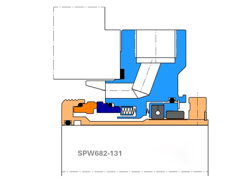
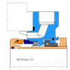
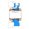
Advanced Stationary Cartridge Seal for API Plan 31 Systems with Restriction Bush Technology
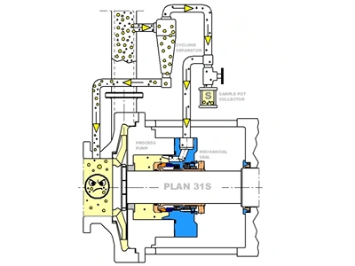
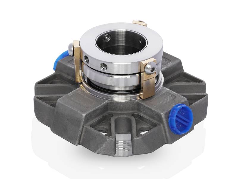
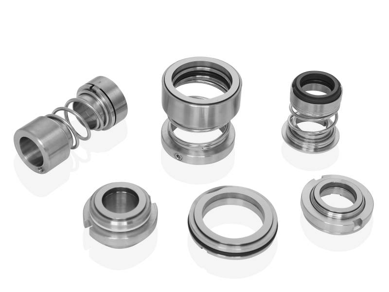
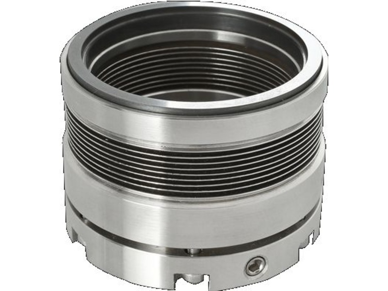
The SPW682-131 from HydroMax Seal is a high-performance single-cartridge mechanical seal, engineered to meet the stringent requirements of API682 standards for critical Oil & Gas sector applications. Designed for compatibility with API Plan 31 systems on API610 V8 and later pumps, it delivers outstanding sealing efficiency in services involving suspended solids and abrasive process fluids.
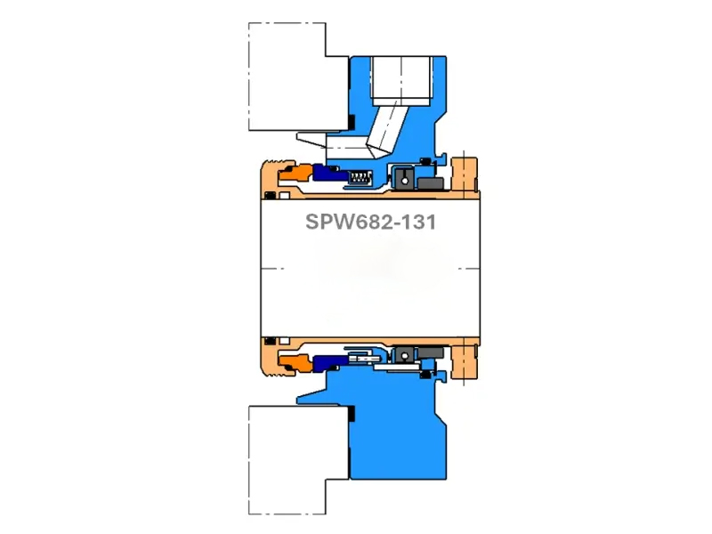
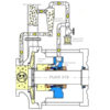
This complete cartridge seal integrates a vortex breaker-equipped gland, along with a dual outboard restriction bushing system—featuring both segmented and floating restriction bushings—to ensure fluid stability, pressure regulation, and improved wear resistance.
Product Description
Design Features
- Flush port configuration tailored for Plan 31 — ensures flush fluid containing particles does not ‘shot blast’ the stationary seal face
- Quench and drain ports support Plan 62 and Plan 52 systems, with ian ntegrated deflector directing steam or buffer fluid to the inboard faces
- Large ½″ NPT seal port orifices for effective flow and system integration
- Integral vortex breakers in the gland plate reduce turbulence and protect sealing interfaces in slurry and particulate applications
- API682-compliant radial clearances for optimal sealing alignment and reliability
- Monolithic seal faces enhance thermal stability and wear resistance in high-temperature environments
- Self-aligning stationary seal face design, optimized for high-speed performance
- Multi-spring layout, with springs isolated from the process fluid to extend seal life
- Unique segmented + floating restriction bush combo ensures superior pressure control and outboard sealing security
- Fully compatible with HydroMax Seal’s Plan 31 Cyclone Separator System and Sample Collection Pot
Technical Specifications
| Seal Shaft Sizes | All sizes supported |
| System Vessel Sizes | 3.17 US gallons and 7.40 US gallons |
| Inboard Seal Face Combinations | TC / TC Carbon / TC Antimony Carbon / RB SiC |
| Gasket Material | Spiral Wound Stainless Steel with Graphite |
| Secondary Sealing Materials | Viton, Alfas, ERP, Kalrez |
| Maximum Shaft Speed | Up to 4,000 RPM |
| Maximum Pressure Rating | Up to 580.2 psig |
| Instrumentation | Designed for integration with Plan 31 piping systems |
| Operating Temperature | Up to 302°F |
The SPW682-131 exemplifies HydroMax Seal’s engineering excellence in slurry-compatible, API682-compliant sealing systems. With innovative restriction bush integration and vortex flow management, it is the go-to solution for challenging applications where reliability, durability, and precision matter most.
Typical Applications & Industry Use Cases
The SPW682-131 is a high-performance single-cartridge mechanical seal, engineered to meet rigorous standards (compliant with API 682) for demanding pump services. It is designed for use with flushing/support systems (such as Plan 31 arrangements) and is well-suited for process fluids containing suspended solids, abrasive media, or particulate-laden slurries.
Industries Served

Oil & gas, petrochemical, and refining
centrifugal pumps in hydrocarbon, solvent, or slurry-handling duties requiring reliable sealing under rigorous conditions.

Chemical processing
pumps handling abrasive or particulate-containing chemicals, corrosive or suspended-solid fluids.

Mining, mineral processing & slurry transfer
pumps for tailings, slurry feed, abrasive slurry transfer where seal reliability and abrasion resistance are critical.

Water treatment, wastewater, or general process industries
applications where particles or contaminants are present and flush/separator support is required for seal-face protection.
Equipment & Use-Case Scenarios
- Pumps built to standard pump-spec frames (e.g, conforming to API 610 V8 and late,r) where flush/separator-seal support (Plan 31) is required for abrasive or contaminated fluids.
- Services with shaft sizes across the supported range, requiring a single-cartridge seal with good mechanical robustness, high speed capability (up to 4,000 RPM), and high pressure tolerance (up to 580.2 psig).
- Applications where flush fluid may contain particles — because the SPW682-131 uses a restriction-bush design, the flush orifice is shaped to avoid “shot-blast” effects on the stationary seal face, improving face life in slurry/fluid-with-solids applications.
- Systems where flexibility in support plan is required (flush, quench, drain), e.g., where operators may use flush or buffer-fluid quench depending on process conditions.
Why It Fits These Applications
- The SPW682-131’s single-cartridge design simplifies installation — factory-assembled with set clearances, reducing installation errors and shortening downtime compared to component seals.
- Its stationary cartridge seal includes a gland with an integral vortex-breaker design and a dual restriction-bush (segmented + floating) arrangement, enhancing pressure regulation and fluid flow stability. This helps manage abrasive or solids-bearing fluids more reliably.
- Large half-inch NPT port orifices facilitate effective flush, quench, or drain fluid flow — enabling flexible integration into flush/separator systems like Plan 31 and enhancing seal-face protection in harsh, solid-containing fluids.
- Material and seal-face options (TC/TC, Carbon/TC, Antimony-Carbon/RB SiC, multiple secondary-seal elastomers) provide adaptability to a range of fluid chemistries and abrasive or corrosive conditions.
Installation Guidelines
Begin with thorough preparation: ensure the pump shaft, seal chamber bore, and gland face are clean, free from scoring or corrosion, and within tolerance. This ensures optimal sealing face alignment.
Carefully insert the SPW682-131 cartridge into the gland or stuffing box. Ensure correct orientation of flush, quench, and drain ports according to your selected support-system plan (e.g., flush/separator Plan 31).
Connect flush/separator piping (including supply, return, vents) and ensure barrier/flushing fluid is clean and properly primed. Vent thoroughly to remove air before initial startup.
After installing, bring up flush/separator fluid circulation first; verify flow, pressure, and cleanliness, then gradually start the pump under monitored conditions. Record baseline values for flush flow, seal-face temperature, shaft speed, and fluid pressure.
Ensure operating conditions (shaft speed, pressure, process fluid properties) remain within the seal’s specified limits (per manufacturer guidelines) for best performance and longevity.
Maintenance & Inspection Best Practices
- Monitor the flush/separator fluid loop: check for a steady flow rate, stable pressure, clean fluid, and no abnormal temperature rise. Any deviation may indicate wear, contamination, or blockage.
- During shutdowns (or scheduled maintenance), where feasible, remove the cartridge for inspection: check seal faces for wear or scoring, examine secondary seals (gaskets/O-rings) for degradation, inspect the gland insert and restriction bush for abrasion or clogging.
- Keep a detailed operating log that tracks fluid properties (solids content, abrasiveness, chemical composition), pump operating conditions (speed, pressure, temperature), flush/separator performance, maintenance events, and any anomalies (vibration, noise, leakage). Use this data for predictive maintenance planning.
- Replace secondary seals and refresh flush/separator fluid and filters on a periodic schedule rather than only on failure; maintaining cleanliness and proper flush/cyclone fluid condition is critical for seal longevity, especially in abrasive services.
- If process conditions change — for instance, higher solids content, more abrasive media, or elevated temperature — re-evaluate seal suitability: consider alternate seal-face materials, elastomers, or an upgraded seal design to improve durability.
Service & Support Options
- Pre-installation consultation: assist in selecting appropriate seal-face materials and elastomers based on fluid chemistry, solids load, and operating conditions.
- Commissioning support: help with flush/separator system setup, correct port orientation, venting, and initial operation monitoring (seal-face temperature, flush flow) to ensure proper start-up.
- Spare-parts kit supply: includes seal faces, O-rings/gaskets, gland-insert components, restriction-bush elements — to support faster maintenance and minimize downtime.
- Upgrade pathways: as service requirements evolve, options exist to switch to more abrasion-resistant face materials or to enhance flushing/support arrangements.
- Preventive-maintenance programme: scheduled inspections, condition-based monitoring, and performance trending to maximize mean time between maintenance and minimise unplanned downtime over the seal lifecycle.
Related Products
Contact HydroMax Seal
Contact HydroMax Seal today for innovative solutions, expert guidance, and over a century of engineering excellence. Your journey to mechanical sealing excellence starts with HydroMax Seal!
E-Mail: sales@hydromaxseal.com
Address: 18511 Beaumont Hwy Building D
Houston, TX
77049